
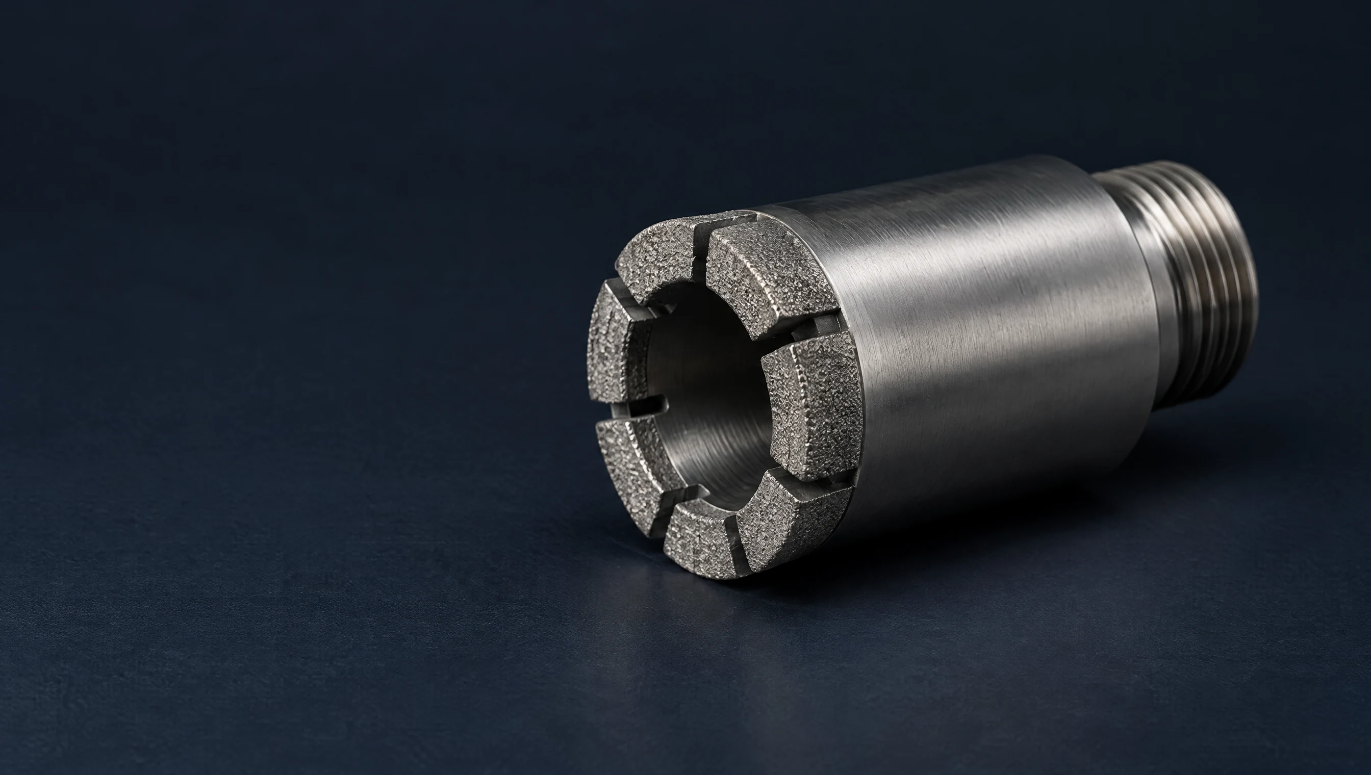
Follow the fluid path
Fluid travels down the drill string, through the core barrel and across the bit face before returning through the annulus. A suitable waterway cannot compensate for a blocked inner assembly, leaking rods or an inadequate return path. Check the entire circuit.
Balance flushing and face contact
Wider passages leave more room for cuttings but reduce the bearing area between channels. The same axial force acting over a smaller contact area produces higher average contact stress. Review load settings when changing the waterway configuration.
Standard channel widths
Channel width is one dimension. Channel depth, quantity and total open area also affect circulation.
Match the geometry to the formation
W uses 3 mm channels for softer ground or less demanding cuttings removal. XW and XXW use 6 and 9 mm channels for harder formations with increasing flushing demands. TP opens from 3 mm at the inner diameter to 6 mm at the outside.
Compare the turbo layouts
WTB adds outer discharge slots for solid to slightly broken rock and small to medium cuttings. XWTB has wider outer slots for slightly broken to broken intervals with larger cuttings. CTB places additional paths at both the inner and outer diameters.
Protect weak core and the hole wall
Face-discharge FD and SFD layouts route fluid toward the cutting face when direct washing of fragile core is a concern. VX is an option for softer formations. Consider fluid viscosity, core condition and borehole stability along with the channel arrangement.
Check the result on the first run
Record flow, pressure, returns, penetration and core recovery. Inspect channel blockage and wear around both gauge surfaces. Pressure rising while returns fall is a circulation problem to investigate before adding load.